Single Frequency Laser Diode

A white circle with a break on the right side, where four red squares form a dotted line extending outward.

mini

ECL

Two gold-colored electronic components with pins are shown. The left one has a cylindrical opening, and the right one is connected to a black cable.

free beam:

40 mW @ 671 nm
80 mW @ 770 nm
80 mW @ 780 nm
80 mW @ 852 nm
80 mW @ 895 nm
100 mW @ 795 nm

with fiber-pigtail:
18 mW @ 770 nm
25 mW @ 780 nm
25 mW @ 795 nm

The image is mostly white with faint, indistinct shapes or marks, making it difficult to discern any clear objects or details.
The image is almost entirely white with no discernible objects, shapes, or text visible.
The image is almost entirely white with faint, barely visible lines or shapes in the center.
The image is too blurry to make out any clear details or objects.
Two gold-colored electronic components with pins are shown. The left one has a cylindrical opening, and the right one is connected to a black cable.

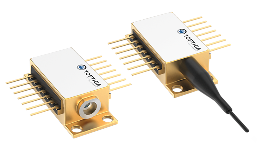
High precision meets high stability & efficiency:

The miniECL is stable laser diode with reduced complexity based on the integration of the (external) cavity and has on top thermal management and beam collimation integrated into the hermetically sealed butterfly package. Now, this truly superior laser diode is available with fiber-pigtail and integrated optical isolator that enables a convenient plug & play. The launch of 770 nm, 780 nm and 795 nm mark the start of the fiber-coupled miniECLs family.

Product Highlights

Small linewidth of 100 kHz

HIGH SMSR (TYP. 50 dB)

Integrated beam collimation

Thermal management by integrated thermoelectric cooler and thermistor

Integrated optical isolator and “plug & play” with fiber-pigtail butterfly
Two gold-colored electronic components with pins are shown. The left one has a cylindrical opening, and the right one is connected to a black cable.

Your Advantages

Line drawing of two electronic components with numbered labels—1 on the left box, 2 and 3 on the left end, and 4 on the right box with a wire attached—ideal for illustrating miniECL circuits in Scrollytelling formats.
A white number 1 centered on a blue circle with a white border, perfect for miniECL designs or as a sleek scrollytelling element.Robustness due to hermetically
sealed butterfly package
A blue circle with a white number 2 in the center, perfect for illustrating steps in a scrollytelling project or marking progress within a miniECL sequence.Very narrow linewidth
for high precision
A solid blue circle with a white number 3 in the center, often featured in miniECL Scrollytelling interfaces.Possibility of wavelength
customization
A white number 4 is centered on a solid blue circular background, making it perfect for miniECL icons or as a step indicator in scrollytelling presentations.Ease of use thanks to high Integration level and “plug & play” option
A white number 5 is centered on a solid blue circle with a thin beige border, making it perfect for miniTA icons or scrollytelling visuals.With evaluation board for
faster testing and preparation
A technical diagram of a miniECL electronic circuit board labeled "TOPTICA," featuring connectors, components, and a probe marked with the number 5.

PLUG & PLAY

Experience Plug & Play as a true game-changer: our highly integrated fiber-coupled miniECL and DFB lasers, paired with the matching miniTA, deliver superior performance while dramatically reducing setup complexity. Compared to traditional macroscopic systems, they save valuable time, offer unmatched stability, and let you get started instantly. Enjoy a fast, reliable solution anywhere with many available wavelengths options.
Line drawing of two miniECL electronic modules connected by a cable with an inline component marked by an arrow, indicating signal direction—ideal for illustrating scrollytelling narratives.
Diagram using scrollytelling to present optical setups for seeder free-beam and fiber-coupled configurations with miniECL and miniTA, illustrating isolator, fiber coupling, AR coating, and cylindrical lenses.

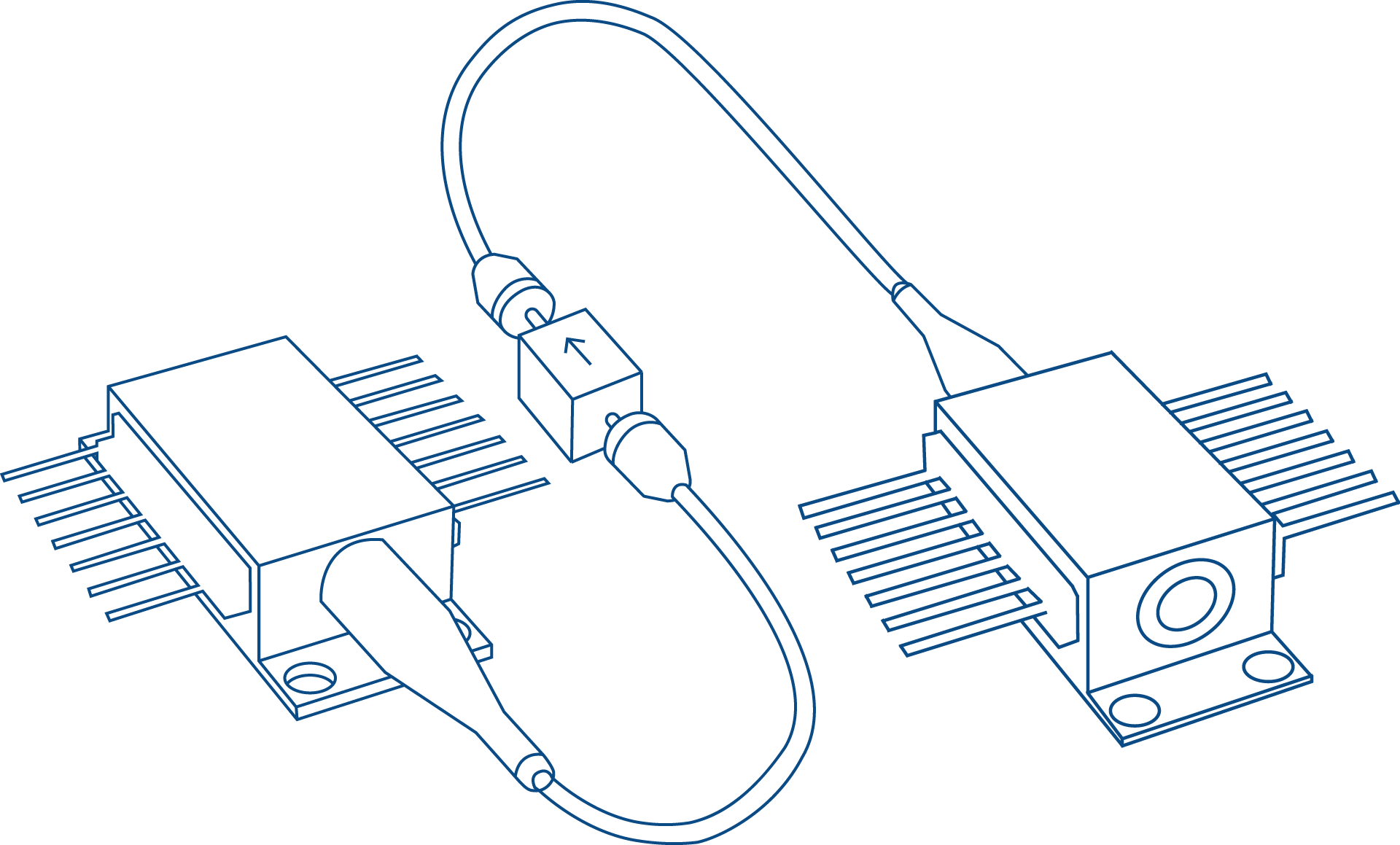
OPERATING A miniECL IS EASILY DONE:

Three men stand smiling at a tech exhibition booth with a robot graphic and signage reading "Thinking Beyond" in the background.

See our interview at SPIE Photonics West 2025!

Three men stand smiling at a tech exhibition booth with a robot graphic and signage reading "Thinking Beyond" in the background.

Download

DATASHEET 671 nm (free-beam)
PDF
DATASHEET 770 nm (free-beam)
PDF
DATASHEET 770 nm (fiber-pigtail)
PDF
DATASHEET 780 nm (free-beam)
PDF
DATASHEET 780 nm (fiber-pigtail)
PDF
DATASHEET 795 nm (free-beam)
PDF
DATASHEET 795 nm (fiber-pigtail)
PDF
DATASHEET 852 nm (free-beam)
PDF
DATASHEET 895 nm (free-beam)
PDF
Flyer
PDF
USER GUIDE
PDF

Applications

Atomic Clock

Metrology

Spectroscopy

img-34
img-35
We shape the future with our unique laser diodes:
With our clients, we go beyond. Together we reach the unreachable.

CONTACT US

We can’t wait to hear your specific requirements or questions. Please contact us any time. We’re here to empower your vision!

Mail

info@toptica-eagleyard.com

Contact Form

MENU

PRODUCTS

APPLICATION

COMPANY

NEWS

CONTACT

CONTACT

EAGLEYARD Photonics GmbH
Rudower Chaussee 29
12489 Berlin

Fon: +49 30 6392 452-0
info@toptica-eagleyard.com

CREDENTIALS

Cookie Settings

Copyright © 2022 TOPTICA EAGLEYARD